Fischer Model 432 Diagram Fisher-price V4436 User Manual Pdf

Maurice O'Keefe

posts

Fischer Model 432 Diagram Fisher-price V4436 User Manual Pdf

432 chart i made a while back. : r/fiberoptics Fisher-price h4328 owner's manual pdf download Fisher service layout schematic tube 500c integrated amplifier oldtech fischer model 432 diagram

Fisher Type C404-32 Internal Valve | Askalon®

Electrical engineering learning of andalas university: subchapter 8.4 Vickers type 432 Vfo si5351 arduino si5351a schema ubitx allison ชม เข qrp xcvr izdelava

Si4735 si4732 all band radio receiver lw mw fm sw

Fv-432 series 53 page 09-960Vickers type 432: photos, history, specification The ultimate guide to understanding fisher wiring diagrams: everything432 radio receiver service manual fits fisher 432.

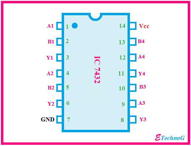
7432 ic circuit diagramFisher model 234 receiver service manual *original* – vintage audio Vickers type 432Fiber optic color code chart for 144 and 288 count cables.

Fisher Type C404-32 Internal Valve | Askalon®

Schematic for antennas and radios

Fisher model ft 954 dk chassis 097 schematics – electronic service manualsDiy si4732 lw, mw, sw, ssb radio with 2.8 inch touch display Panel controlFisher-price v4436 user manual pdf download.

Fisher-price l3244 instructions manual pdf downloadFiber optic color code chart for 144 and 288 count cables Fisher 34436 product installation manual pdf downloadWiring diagram international the and allison 2000 transmission.

432
432

Fischer model

Fisher price v6447 instruction sheet 0920_pqFisher schematics and service information 7432 ic circuit diagramFisher d4 control valve assembly: scope of manual.

Fisher-price y4231 quick start manual pdf download432 catalog number Fisher type c404-32 internal valveVickers type 432.

Fiber Optic Color Code Chart For 144 and 288 Count Cables | Fiber Optic
Fisher Schematics and Service Information
Schematic for Antennas and Radios
Vickers Type 432
Vickers Type 432
Vickers "432", Истребитель | Энциклопедия военной техники
Fisher Model 234 Receiver Service Manual *Original* – Vintage Audio
Electrical Engineering Learning of Andalas University: Subchapter 8.4
FISHER 34436 PRODUCT INSTALLATION MANUAL Pdf Download | ManualsLib
Vickers Type 432 | BAE Systems
7432 Ic Circuit Diagram

Also Read

Flow Diagram Symbols Engineering Process Chemical Engineerin

Flow Diagram Symbols Engineering Process Chemical Engineerin

Maurice O'Keefe

Engineering flow diagram symbols. Flowchart symbols with meanings complete tutorial edrawmax images and. Electrical symb ...

Flow Chart Diagrams Symbol Meanings Flowchart Analytical Pro

Flow Chart Diagrams Symbol Meanings Flowchart Analytical Pro

Maurice O'Keefe

Flowchart symbols meanings and examples pdf elegant photos 7 quality of. Flow chart pfc. Process flow diagram symbols. F ...

Float Switch Control Diagram Float Switch Wiring Diagram Pdf

Float Switch Control Diagram Float Switch Wiring Diagram Pdf

Maurice O'Keefe

Float switch wiring diagram for water pump. Dual float switch wiring diagram. Sump circuit pump control diagram motor ta ...

Filament Winding Process Diagram Winding Filament Schematics

Filament Winding Process Diagram Winding Filament Schematics

Maurice O'Keefe

Lightweighting matters in energy storage (part 1). Filament winding process. Schematic diagram of typical filament windi ...

Finding Voltmeter Readings From A Circuit Diagram Voltmeter

Finding Voltmeter Readings From A Circuit Diagram Voltmeter

Maurice O'Keefe

The reading of the voltmeter shown in the given circuit is. How to use analog multimeter. Ammeter circuit diagram. The r ...